ASME B16.5 threaded flanges, Class 600
Every size in the table, in mm, with a 3D model drawn from the same figures. See threaded flanges for materials, standards and the marking.
3D model
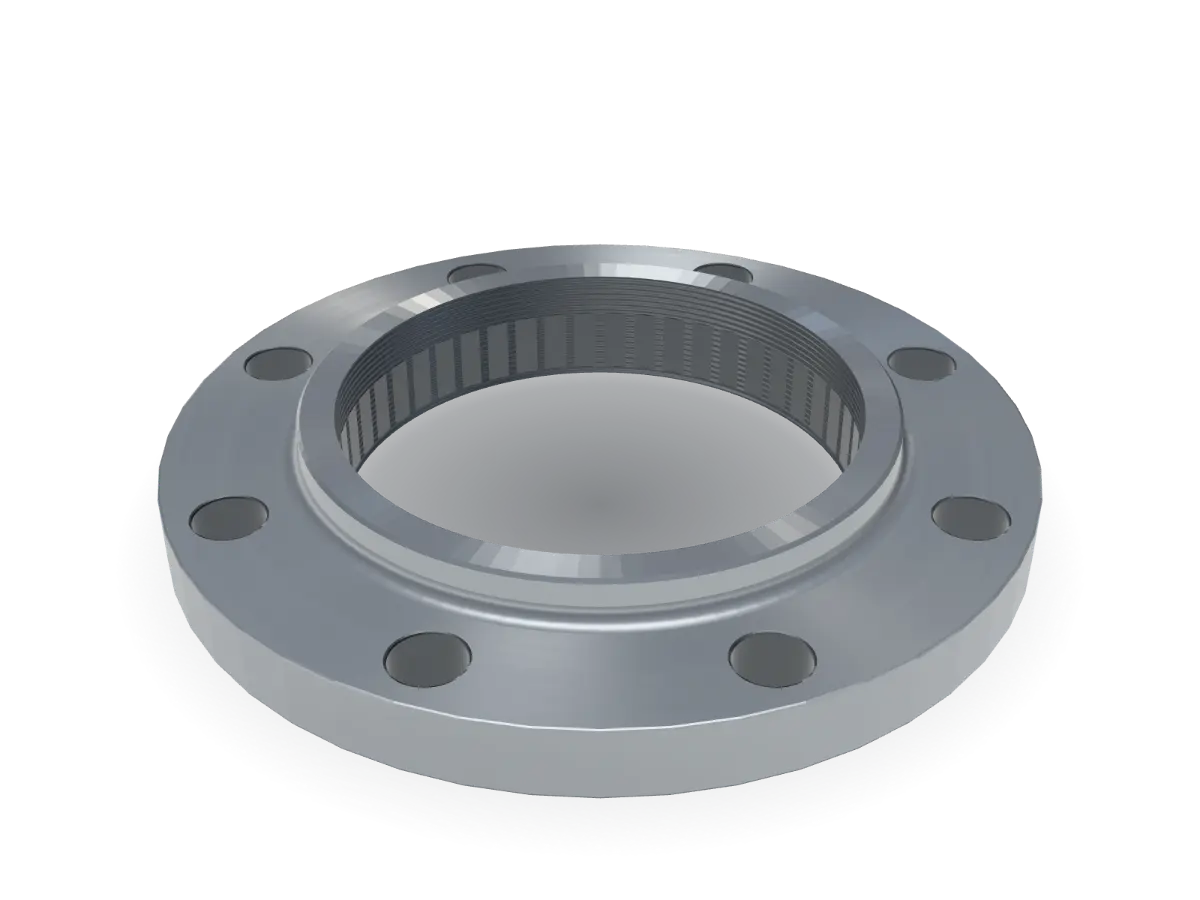
6" Class 600 threaded
Key dimensions in mm, ASME B16.5
- O
- Flange diameter
- 355
- Tf
- Flange thickness
- 47.7
- X
- Hub diameter
- 222
- Y
- Length through hub
- 74
- T
- Thread length
- 51
- Q
- Counterbore
- 171.4
- R
- Raised face diameter
- 215.9
- Tr
- Raised face height
- 7
- W
- Bolt circle (PCD)
- 292.1
- d
- Bolt hole diameter
- 28.6
- n
- Number of holes
- 12
- kg
- Weight, approx.
- 32
Dimensions
Units
Swipe the table sideways for every column. Choose a size to show it in the viewer.
| NPSSize | DNNominal size | OFlange diameter | TfFlange thickness | XHub diameter | YLength through hub | TThread length | QCounterbore | RRaised face diameter | TrRaised face height | WBolt circle (PCD) | dBolt hole diameter | nNumber of holes | kgWeight, approx. | Enquiry list |
|---|---|---|---|---|---|---|---|---|---|---|---|---|---|---|
| 15 | 95 | 14.3 | 38 | 29 | 16 | 23.6 | 34.9 | 7 | 66.7 | 15.9 | 4 | 1 | ||
| 20 | 115 | 15.9 | 48 | 32 | 16 | 29 | 42.9 | 7 | 82.6 | 19 | 4 | 1.6 | ||
| 25 | 125 | 17.5 | 54 | 34 | 18 | 35.8 | 50.8 | 7 | 88.9 | 19 | 4 | 1.8 | ||
| 32 | 135 | 20.7 | 64 | 36 | 21 | 44.4 | 63.5 | 7 | 98.4 | 19 | 4 | 2.6 | ||
| 40 | 155 | 22.3 | 70 | 39 | 23 | 50.6 | 73 | 7 | 114.3 | 22.2 | 4 | 3.3 | ||
| 50 | 165 | 25.4 | 84 | 44 | 29 | 63.5 | 92.1 | 7 | 127 | 19 | 8 | 3.9 | ||
| 65 | 190 | 28.6 | 100 | 48 | 32 | 76.2 | 104.8 | 7 | 149.2 | 22.2 | 8 | 6 | ||
| 80 | 210 | 31.8 | 117 | 53 | 35 | 92.2 | 127 | 7 | 168.3 | 22.2 | 8 | 7.4 | ||
| 90 | 230 | 35 | 133 | 56 | 40 | 104.9 | 139.7 | 7 | 184.2 | 25.4 | 8 | not listed | ||
| 100 | 275 | 38.1 | 152 | 61 | 42 | 117.6 | 157.2 | 7 | 215.9 | 25.4 | 8 | 17 | ||
| 125 | 330 | 44.5 | 189 | 67 | 48 | 144.4 | 185.7 | 7 | 266.7 | 28.6 | 8 | 26.5 | ||
| 150 | 355 | 47.7 | 222 | 74 | 51 | 171.4 | 215.9 | 7 | 292.1 | 28.6 | 12 | 32 | In the viewer | |
| 200 | 420 | 55.6 | 273 | 83 | 58 | 222.2 | 269.9 | 7 | 349.2 | 31.7 | 12 | 46 | ||
| 250 | 510 | 63.5 | 343 | 93 | 66 | 276.2 | 323.8 | 7 | 431.8 | 34.9 | 16 | 74 | ||
| 300 | 560 | 66.7 | 400 | 99 | 70 | 328.6 | 381 | 7 | 489 | 34.9 | 20 | 90 | ||
| 350 | 605 | 69.9 | 432 | 101 | 74 | 360.4 | 412.8 | 7 | 527 | 38.1 | 20 | 108 | ||
| 400 | 685 | 76.2 | 495 | 113 | 78 | 411.2 | 469.9 | 7 | 603.2 | 41.3 | 20 | 150 | ||
| 450 | 745 | 82.6 | 546 | 124 | 80 | 462 | 533.4 | 7 | 654 | 44.4 | 20 | 188 | ||
| 500 | 815 | 88.9 | 610 | 134 | 83 | 512.8 | 584.2 | 7 | 723.9 | 44.4 | 24 | 230 | ||
| 600 | 940 | 101.6 | 718 | 147 | 93 | 614.4 | 692.2 | 7 | 838.2 | 50.8 | 24 | 325 |
Dimensions in mm, for reference. Tolerances and full requirements as per the applicable standard. Confirm against your specification before ordering.
Source: Shiv Shakti Machine Tools Flange Catalogue, edition 2026 (draft), page 10, weights page 15. “–” means the catalogue lists no value.
[CONFIRM: table checked and signed off by the owners (unverified)][CONFIRM: whether the flange thickness includes the raised face]