DIN weld neck flanges, PN 6
Every size in the table, in mm, with a 3D model drawn from the same figures. See weld neck flanges for materials, standards and the marking.
3D model
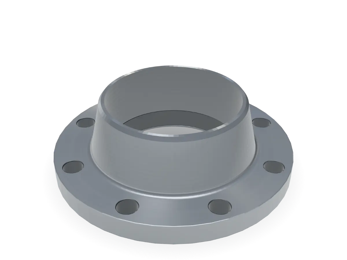
DN 150 PN 6 weld neck
Key dimensions in mm, DIN 2631
- D
- Flange diameter
- 265
- b1
- Flange thickness
- 18
- d1
- Weld end diameter, series 1
- 168.3
- d1
- Weld end diameter, series 2
- 159
- d3
- Hub diameter, series 1
- 184
- d3
- Hub diameter, series 2
- 172
- s
- Wall thickness
- 4.5
- r1
- Radius
- 10
- h1
- Length through hub
- 48
- h3
- Length
- 12
- d4
- Raised face diameter
- 202
- f
- Raised face height
- 3
- k
- Bolt circle (PCD)
- 225
- d2
- Bolt hole diameter
- 18
- Thrd
- Bolt thread
- M 16
- n
- Number of holes
- 8
- kg
- Weight, approx.
- 5.2
Dimensions
Swipe the table sideways for every column. Choose a size to show it in the viewer.
| DNSize | DFlange diameter | b1Flange thickness | d1Weld end diameter (1) | d1Weld end diameter (2) | d3Hub diameter (1) | d3Hub diameter (2) | sWall thickness | r1Radius | h1Length through hub | h3Length | d4Raised face diameter | fRaised face height | kBolt circle (PCD) | d2Bolt hole diameter | ThrdBolt thread | nNumber of holes | kgWeight, approx. | Enquiry list |
|---|---|---|---|---|---|---|---|---|---|---|---|---|---|---|---|---|---|---|
| 75 | 12 | 17.2 | 14 | 26 | 22 | 1.8 | 4 | 28 | 6 | 35 | 2 | 50 | 11 | M 10 | 4 | 0.3 | ||
| 80 | 12 | 21.3 | 20 | 30 | 28 | 2 | 4 | 30 | 6 | 40 | 2 | 55 | 11 | M 10 | 4 | 0.4 | ||
| 90 | 14 | 26.9 | 25 | 38 | 35 | 2.3 | 4 | 32 | 6 | 50 | 2 | 65 | 11 | M 10 | 4 | 0.6 | ||
| 100 | 14 | 33.7 | 30 | 42 | 40 | 2.6 | 4 | 35 | 6 | 60 | 2 | 75 | 11 | M 10 | 4 | 0.7 | ||
| 120 | 14 | 42.4 | 38 | 55 | 50 | 2.6 | 6 | 35 | 6 | 70 | 2 | 90 | 14 | M 12 | 4 | 1.1 | ||
| 130 | 14 | 48.3 | 44.5 | 62 | 58 | 2.6 | 6 | 38 | 7 | 80 | 3 | 100 | 14 | M 12 | 4 | 1.2 | ||
| 140 | 14 | 60.3 | 57 | 74 | 70 | 2.9 | 6 | 38 | 8 | 90 | 3 | 110 | 14 | M 12 | 4 | 1.3 | ||
| 160 | 14 | 76.1 | not listed | not listed | 88 | 2.9 | 6 | 38 | 9 | 110 | 3 | 130 | 14 | M 12 | 4 | 1.7 | ||
| 190 | 16 | 88.9 | not listed | not listed | 102 | 3.2 | 8 | 42 | 10 | 128 | 3 | 150 | 18 | M 16 | 4 | 2.7 | ||
| 210 | 16 | 114.3 | 108 | 130 | 122 | 3.6 | 8 | 45 | 10 | 148 | 3 | 170 | 18 | M 16 | 4 | 3.2 | ||
| 240 | 18 | 139.7 | 133 | 155 | 148 | 4 | 8 | 48 | 10 | 178 | 3 | 200 | 18 | M 16 | 8 | 4.5 | ||
| 265 | 18 | 168.3 | 159 | 184 | 172 | 4.5 | 10 | 48 | 12 | 202 | 3 | 225 | 18 | M 16 | 8 | 5.2 | In the viewer | |
| 320 | 20 | 219.1 | not listed | not listed | 236 | 5.9 | 10 | 55 | 15 | 258 | 3 | 280 | 18 | M 16 | 8 | 7.8 | ||
| 375 | 22 | 273 | 267 | 290 | 282 | 6.3 | 12 | 60 | 15 | 312 | 3 | 335 | 18 | M 16 | 12 | 10.8 | ||
| 440 | 22 | 323.9 | not listed | not listed | 342 | 7.1 | 12 | 62 | 15 | 365 | 4 | 395 | 22 | M 20 | 12 | 14 | ||
| 490 | 22 | 355.6 | 368 | not listed | 385 | 7.1 | 12 | 62 | 15 | 415 | 4 | 445 | 22 | M 20 | 12 | 18.5 | ||
| 540 | 22 | 406.4 | 419 | not listed | 438 | 7.1 | 12 | 65 | 15 | 465 | 4 | 495 | 22 | M 20 | 16 | 21.2 | ||
| 645 | 24 | 508 | not listed | not listed | 538 | 7.1 | 12 | 68 | 15 | 570 | 4 | 600 | 22 | M 20 | 20 | 28.6 |
Dimensions in mm, for reference. Tolerances and full requirements as per the applicable standard. Confirm against your specification before ordering.
Source: Shiv Shakti Machine Tools Flange Catalogue, edition 2026 (draft), page 13. “–” means the catalogue lists no value.
[CONFIRM: table checked and signed off by the owners (unverified)][CONFIRM: whether the flange thickness includes the raised face]